

Making your own audio cables can be a rewarding thing. But also sometimes it is necessary.
In the rack for my PA system I need to go from the XLR outputs of my mixer to the 1/4 inch inputs on my power amp. However because of the tight space of the lid and back door of the case both connectors need to be right angle connectors.
I couldn’t even find any options of cables that are right angle female XLR to right angle TRS so really the only option is to make my own.
Help Support This Content!
Balanced audio cables have two wires and a shield for three total connectors. On XLR cables the pins are usually labeled 1,2, and 3. Depending on which end you are looking at the numbers can appear left to right, or right to left. Just something that can trip you up and is something to watch out for.


Links to connectors used in this article:
Right angle XLR connector: https://amzn.to/2QNnAR9
Right angle TRS connector: https://amzn.to/2ty5wCi
To wire up the XLR connector end:
- Ground / Shield
- Hot Signal (or positive signal)
- Cold Signal (or negative signal)
Wiring this end is pretty straight forward, you just need to strip back the cable and the individual wires and connect them to the correctly numbered solder tabs.
Make sure that you slide on the necessary pieces of the connector before soldering up the cable!

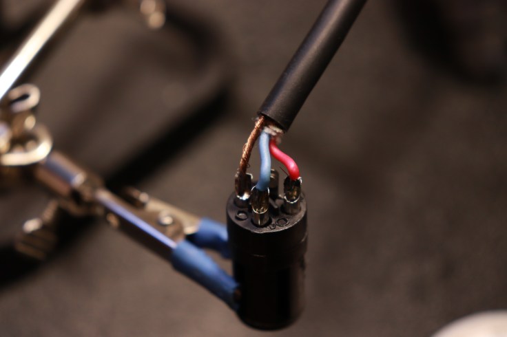
Note the stray wire coming off the red wire (pin 2). This should be cleaned up that it cannot short out to another pin.
Once we put the XLR connector back to together it is time to solder up the TRS end of the cable. TRS stands for tip, ring, and sleeve. An unbalanced 1/4 inch cable is only TS, or tip and sleeve. Adding the ring to this connector makes it a balanced cable. so the pin out for a TRS cable is:
- Ground / Shield = Sleeve
- Hot Signal = Tip
- Cold Signal = Ring
Sometimes this can be difficult to figure out which solder tab is associated with the various connector. So you can use a multimeter in continuity mode to figure out which tabs go to tip, ring and sleeve.

Once we know that we can solder up the wires to the correct tabs.

After assembling the connector we can test the cable to make sure that it will work. With our multimeter still in continuity mode we can make sure pin 1 of the XLR is connected to the sleeve of the TRS connector and nothing else. Pin 2 to the tip and nothing else. And pin 3 to the ring and nothing else. With that check out of the way the cable should work great and fit perfectly where we need it to in the equipment rack.
For a video walkthrough of this process check out the tutorial below:

Leave a comment